Work with Node Connectors and Events
Connections are made using connectors within the nodes. Connectors appear when you point, hold and drag a node edge towards a target node (except the Start node, as it does not accept inputs). When you are about to connect an event to the target node, the target node is highlighted. A dotted line appears till you connect the event. After the event is connected, the dotted line turns into a continuous line. The figure below illustrates these steps.

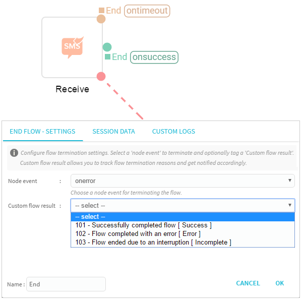
Each node can have multiple incoming and limited outgoing edge that are used to configure events. Each node has its different set of outgoing events called 'Node Edges'. If the node does not have an outgoing edge, then it must be configured to end the flow.
-
To configure a node, drag-drop an edge anywhere on the screen and select a relative event. The below image represents a configured node.
-
You can connect a source node to a target node, however, you cannot loop back to the immediat previous node.
-
To modify a configured event, select and double-click the node/connector and modify the action required at the respective location, click Save to complete.
-
To delete a node or a connector, point, and select the respective node/connector, press delete button on the keyboard. The selected node/connector is deleted and disappears from the flow canvas.

For easy comprehension of the flow, based on the node event, the connectors are displayed in different colors.
- A green color line indicates the flow continuation events in the flow.
- An orange color line indicates time-bound events of the node.
- A red color line indicates the error events that are used to handle errors or end the flow.

Updated about 6 years ago